NEMESIS TCS
Programming/Software
Communication-Interface
As explained inside the Plug and Play section, if you want to make the all the necessary adjustments of the Nemesis TCC System on your own, you need the Communication-Interface, which comes of course with the WinTC software on CD

To be able to program all the necessary Parameters yourself, you need the COMMUNICATION
INTERFACE with it's Software.
If this is maybe too much for you, or you feel uncomfortable to do this
yourself, if you fear you can make a mistake, then there are still a couple of
Solutions:
after you've mounted everything you move to a Dealer to make the correct adjustments (the dealer or you then needs to have the Communication Interface)
There is no Dealer around, but you have the communication Interface - then I be able to set the correct Values for you ONLINE, means you need maybe Skype, or a Phone, and Teamviever - and I can set the correct Values from my computer into your computer into the TCS Module
Generally:
You can not see or rework the internal Algorithms of the Nemesis TCS, which is a good thing for most people. But what you can, and what you have to adjust:
the circumference of the Tyres
the Impulses per wheel-rev (max 20)
you can load different Slip Maps, as even same sized tyres are different in slip-behavior
Quickshifter settings where you can chose from Retard to Cut
Shift-Input Settings
Settings for Pitlimiter
Next then via the TC Data screen you can check the System Values as real Time Data
The Nemesis WinTC Software
After you have installed the Software you've got this Basic screen

Win-TC / Pit speed limiter
The pit speed limiter can be activated by shorting together the 2 wires of the connector called PIT on the chassis wiring loom supplied in your kit. Any type of ‘normally open’ switch can be used.
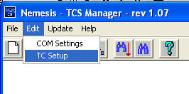
From the upper menu select Edit, followed by TC Setup
to locate the Pit limiter settings.
The Pit lane speed limiter uses a the following parameters:
• Enable PIT Limiting. Tick the box to activate the pit limit
system.
• Speed limit (km/h) – At this speed the TCS will start to cut cylinders which
will be felt as a misfire.
• dSpeed range (km/h) – This value is added to the Speed Limit to create an
upper boundary. If the bike reaches Speed limit + dSpeed range (eg: 60+6 =
66km/h) the majority of coil signals are cut. Between these 2 levels the cut
becomes progressively more severe.
The Pit limiter option is active whenever the bike front speed is between 30 and 100km/h. The user must push and hold the Pit limiter switch for the system to remain active. When the Pit limiter is active all blue LEDs are active on the TC-Pod for the duration that the button is held down.
If the button is held down for longer than 20 seconds it is presumed that the input or switch is damaged and a diagnostic message will appear on the Pod display. To save your changes, proceed as follows.
• Press OK to save your changes.
• Select File then Save from the upper menu, apply a new file name using the
sequence suggested as follows:
- if your Basic File is i.E.: 110_848_1_S01_R01.S19
- then your MODIFIED File ( lets say it's your FIRST modified File) should be
named: 110_848_1_S01_R01_U01.S19
• Press this button  to update
the TCS module with your new map file.
to update
the TCS module with your new map file.
• This process will take approx 6 seconds.
• During the transmission process and for 4 seconds afterwards the TC-Pod will
flash an Error 5 and the bike cannot be started. This is perfectly normal.
The switch status (OFF or ON) can be viewed in real time within the WinTC View Data window
Win-TC / Wheel speed
The Nemesis-TCS uses a Hall sensor fitted to the front and rear wheel speed to obtain wheel speed data via a dedicated trigger disk with 10 teeth. Under no circumstances must this be modified in any way. From the upper menu select Edit, followed by TC Setup to locate the wheel speed settings.
Rear Speed - All Ducati in recent years have a very good quality Hall sensor fitted to the rear wheel which we link up to within the chassis loom in your kit. This signal remains linked to the ECU and is not affected by linking also to the TCS.
Front speed – As part of your bike kit you will receive a new sensor, mounting bracket and a set of trigger teeth for using on the front wheel. These components should not be modified in any way, nor should any other pick-up devices or speed triggers be used on this wheel. Any attempt to modify this or use alternative pick-ups may seriously affect the system integrity.
Front speed
• Teeth per revolution – Define the number of pick up teeth for one wheel revolution.
• Circumference – See note below.
Rear speed
• Teeth per revolution – Define the number of pick up teeth for one wheel revolution.
• Circumference – See note below.
Circumference
These values are pre-defined by us in order to provide you with an accurately
matched set of speed data when the bike is banked over.
It should also be noted that we do not guarantee the speed to be correct, as we
are more concerned with the relative speed of the front and rear wheels.
IMPORTANT
The tyre circumference you see here may not be exactly what you
expect based on any static´measurements you make. The value here is the rolling
circumference when the bike is leaned over and under load.
The actual measured speed does not need to be very accurate; it only needs to be
comparable with the rear wheel speed so that the front speed is 0.5% lower at
the middle of the corner before the throttle is applied.
Unless you use a data logger to measure this information using the ‘CAN stream’
we provide, your best solution for making adjustments yourself is to follow
these rules, or use values provided by us and our dealers. Remember to try
different map levels first.
Problem...............TCS activity is insufficient at the middle of the corner when throttle is applied.
Solution ...............Reduce the front speed calibration in 0.5% steps until you achieve the results you want. Example : 1850mm reduced by 0.5% = 1841 (1850 x 0.995 = 1841 rounded up)
Problem...............TCS activity is excessive at the middle of the corner when throttle is applied.
Solution ...............Increase the front speed calibration in 0.5% steps until you achieve the results you want.
Press OK to save your changes.
• Select File then Save from the upper menu, apply a new
file name using the sequence suggested as follows:
- if your Basic File is i.E.: 110_848_1_S01_R01.S19
- then your MODIFIED File ( lets say it's your FIRST modified File) should be
named: 110_848_1_S01_R01_U01.S19
• Press this button to update the TCS
module with your new map file.
• This process will take approx 6 seconds.
• During the transmission process and for 4 seconds afterwards the TC-Pod will
flash an Error 5 and the bike cannot be started. This is perfectly normal.
Note that in the majority of cases it is not necessary to adjust this yourself as we have already defined these parameters for a wide variety of tyre makes, models and sizes.
Win-TC / Throttle
From the upper menu select Edit, followed by TC Setup to locate the
throttle setting.
For the majority of users we apply a default value for throttle activation as
part of the map for your bike and adjustment is not necessary. However,
users of Win-TC are able to define this parameter to fix the threshold
slightly above the closed throttle value.
Firstly the value of closed throttle should be viewed using the View Data
window, See below "TC view Data". The Throttle activation point should then be
adjusted to 2% above the closed throttle value.
To save your changes, proceed as follows.
• Press OK to save your changes.
• Select File then Save from the upper menu, apply a new file name using the
sequence suggested as follows:
- if your Basic File is i.E.: 110_848_1_S01_R01.S19
- then your MODIFIED File ( lets say it's your FIRST modified File) should be
named: 110_848_1_S01_R01_U01.S19
• Press this button to update the TCS module with your new map file.
• This process will take approx 6 seconds.
• During the transmission process and for 4 seconds afterwards the TC-Pod will
flash an Error 5 and the bike
cannot be started. This is perfectly normal.
Analogue throttle information is picked up directly from the sensor and
pre-defined within the TCS map. Typically the
traction control activation point is preset at approx 3deg of throttle.
We apply default calibrations for the throttle based on average data from your
model of bike.
Win-TC / Quick shifter
Basically this means that whenever the signal and
the ground wire of the loom connector are linked together you will get a quick
shift event.
From the upper menu select Edit, followed by TC Setup to locate the Quick Shift
setting.
Within the Win-TC software you can choose to have
Cut only
Retard only
Cut and retard
Cut / Retard time
If Cut mode
is selected the ignition is cut for duration chosen by the user.
1) 40msec
2) 45msec
3) 50msec
4) 55msec
5) 60msec
6) 65msec
7) 70msec
8) 75msec
The cut starts as soon as the signal is seen from the shifter system. Further
shifts are inhibited for 300msec after the end of the preceding shift.
Ignition Retard
.........................................................
If Retard only mode
is chosen the ignition continues to fire the coils but with a retard applied, as
chosen by the user.
The duration for the retard is defined by the Cut / Retard time above
1) No retard
2) 5deg retard
3) 10deg retard
4) 15deg retard
5) 20deg retard
6) 30deg retard
7) 40deg retard
8) 50deg retard
Retard return slope
– Step time
The retard return slope defines how fast
the ignition returns to normal timing after a ‘Retard’
event and is defined in
this table. This ramp allows a gradual return to full power rather than a rapid
return which is beneficial especially in
the wet. The Step time is how long each return step is held for. And the Step
value is how many degrees of ignition
advance per step
1) No ramp return
2) 5msec
3) 10msec
4) 15msec
5) 20msec
6) 25msec
Notes
• The default setting is:
• Ignition Cut – 65msec.
• Retard – 15deg.
• 5 degree every 10msec ‘return to normal’ slope.
• The use of a large retard can cause post combustion in the exhaust leading to
banging.
• One 720 degree engine rotation at 11000rpm = 10.9msec.
..........................................................
The shift input can be programmed for use with the following type of switch:
Switch that is ‘normally closed’ and opens
the circuit when the shift level is pressed such as the Ducati Corse
load-sensing lever.
Switch that is ‘normally open’ and closes the
circuit when the shift level is pressed such as the Nemesis shifters.

The quick shifter status can be viewed in real time within the WinTC View Data
window. To save your changes, proceed as follows.
• Press OK to save your changes.
• Select File then Save from the upper menu, apply a new file name using the
sequence suggested above
• Press this button to update the TCS module
with your new map file.
• This process will take approx 6 seconds.
• During the transmission process and for 4 seconds afterwards the TC-Pod will
flash an Error 5 and the bike
cannot be started. This is perfectly normal.
....................................
Examples.
In this example I have chosen a cut and retard. The ignition is removed for 60msec. When the ignition is re-activated there is a ‘retard’ of 30deg to make the power come back in at a lower level, and then a slope to return the power back to normal levels. This stops the bike breaking traction after a shift by applying all of the power very quickly.
Note that the following diagrams shows a sloped return, in reality these are steps.
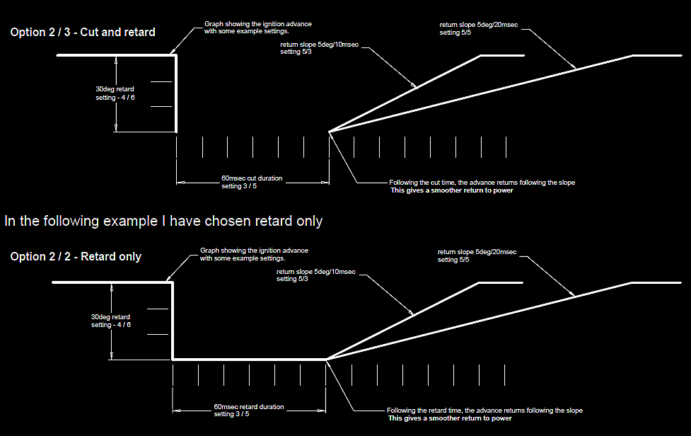
There is no cut, just a time period with the ignition retarded by 30deg, then the slope back. This option can make a softer gear change.
Win-TC / Files
From the upper menu select File / Open and select the .s19 file that you wish to work on. Make any changes that you need as per the previous pages.
Use the Save command to save these files. It is advised
that you do not change any element of the existing file naming sequence as this
helps us to identify later on what has been used as a base setting. You are of
course free to add extra name characters preceding the .s19

To transmit a new map file to the TC module.
• Turn on bike power.
• Connect the WinTC-USB adaptor between your PC and Bike.
• Wait until the TC-Pod has completed the start up sequence.
• Press the Send Parameters option, or this button -------------
• A progress bar will appear and indicate when the transmission is completed.
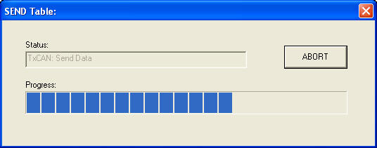
• During the transmission process and for 4 seconds afterwards the TC-Pod will flash an Error 5 and the bike cannot be started. This is perfectly normal.
TC View Data
From the upper menu select this icon
 to open the following window.

This window provides real time data from the primary system inputs and allows you to check that the installation hasbeen done correctly.
FW Release ...................Internal firmware release of the
TC module.
MAP Name.....................Name of the map as loaded by you or your dealer.
MAP Rev ........................Incremental counter relating to the map release.
TC Data
Vbat ................................Internal monitor of system
voltage (may be up to 200mV different from the battery).
Position...........................Internal position sensor with value offset
specific to the bike installation.
Throttle ..........................Internally calibrated throttle angle, should
be between minus 2 and plus 2.5 with the throttle closed. If not, contact your
dealer. The max value can be anywhere between 90 and 110 and is mostly not
important.
Front speed ....................Value in Kmh – minimum measurable value is
11km/h.
Rear speed.....................Value in Kmh – minimum measurable value is
11km/h.
Quick shift ......................Turns from OFF to ON when the signal is
applied.
Speed limit......................Pit limiter switch status OFF or ON.
The bar graph at the bottom of the screen moves continually when the system is transmitting data to WinTC.The TC-Pod will flash an Error.
Spark Advance map
The Nemesis-TCS uses variable amounts ignition retard as the initial response to slip control therefore the ignition map within the ECU can play an important role in the amount of power reduction achieved at each slip response level. Any change to your ECU advance mapping can have a significant affect on the TCS response and control.